A few weekends ago I had the wiring sorted - functioning - using the eBay switchgear. But, it didn’t look quite right on the bike, not “factory” enough, so I went looking for another option.
I found another eBay set that looked the part and decided to roll the dice on the key switch - the turn signals. You see, I’ve been converting the 3-position headlight switches into turn signals. Its usually pretty simple IF the switch has the right contacts.
This is the set I purchased. There’s' a few sets that appear similar, but this so far is “usually” pretty well built. The headlight switch in this set has the contacts available to convert it to a turn signal switch, but the actual switch housing doesn’t hold together well when soldering… or, at least the one I bought didn’t.
My work around was to take the turn signal switch assembly out of THIS eBay switchgear set, and squeeze it into the housing I intended to use. Worked a treat and it looks acceptable.
The other issue with swapping out the SWM switchgear is throttle cables. The bike uses two throttle cables, and I couldn’t find a set of switchgear that was suitable for my required modifications and accepted two throttle cables. The other issues have been how the throttle tube fits in the housing, and the throttle cable length. Fortunately, the set I’m using now fitted perfectly - using the bikes original push cable as the new pull cable.
Repurposing the kill switch as a Hi/Lo Beam switch requires a switching relay, and switching relays take up valuable space inside the headlight shell. My original intention of retaining controls so a “two armed” rider can ride the bike have been abandoned. The SWM is now my bike and my bike only. Fortunately, all mods at this stage a reversible.

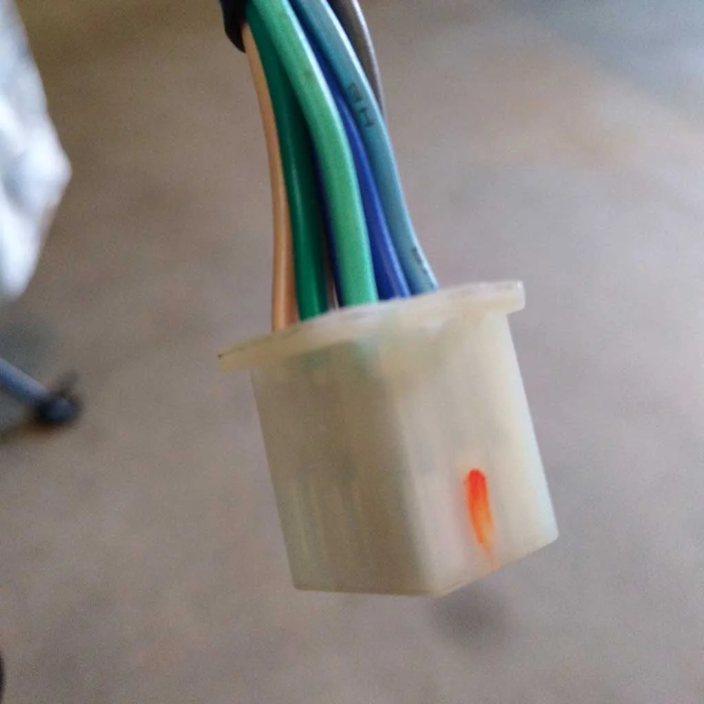
The turn signal switch assembly was taken from this switchgear…

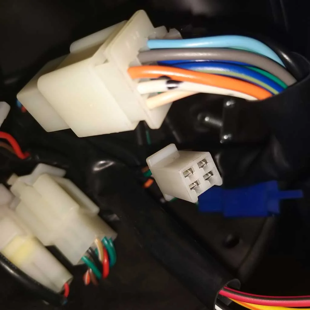
… and transplanted into the Right Hand assembly of this switchgear set.

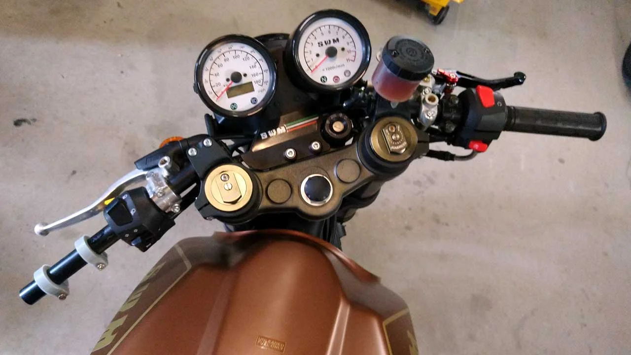
Finished setup.

How it all works now.

The first set of modified switchgear - worked, but not the best look on this bike.