
I’ve been tasked with modeling a housing that replaces the Honda Goldwings original stereo with a different unit. Watch for updates.


Controls updated
All controls wired up and functioning - VIDEO

Current state of the bars.
Controls - Done.
A few weekends ago I had the wiring sorted - functioning - using the eBay switchgear. But, it didn’t look quite right on the bike, not “factory” enough, so I went looking for another option.
I found another eBay set that looked the part and decided to roll the dice on the key switch - the turn signals. You see, I’ve been converting the 3-position headlight switches into turn signals. Its usually pretty simple IF the switch has the right contacts.
This is the set I purchased. There’s' a few sets that appear similar, but this so far is “usually” pretty well built. The headlight switch in this set has the contacts available to convert it to a turn signal switch, but the actual switch housing doesn’t hold together well when soldering… or, at least the one I bought didn’t.
My work around was to take the turn signal switch assembly out of THIS eBay switchgear set, and squeeze it into the housing I intended to use. Worked a treat and it looks acceptable.
The other issue with swapping out the SWM switchgear is throttle cables. The bike uses two throttle cables, and I couldn’t find a set of switchgear that was suitable for my required modifications and accepted two throttle cables. The other issues have been how the throttle tube fits in the housing, and the throttle cable length. Fortunately, the set I’m using now fitted perfectly - using the bikes original push cable as the new pull cable.
Repurposing the kill switch as a Hi/Lo Beam switch requires a switching relay, and switching relays take up valuable space inside the headlight shell. My original intention of retaining controls so a “two armed” rider can ride the bike have been abandoned. The SWM is now my bike and my bike only. Fortunately, all mods at this stage a reversible.

The turn signal switch assembly was taken from this switchgear…

… and transplanted into the Right Hand assembly of this switchgear set.

Finished setup.

How it all works now.

The first set of modified switchgear - worked, but not the best look on this bike.
The Arm is complete - and its perfect
Dan has delivered. The arm parts arrived yesterday and first testing was today and the improvements are significant.
The most noticeable improvement has been at the shock absorber - it’s now doing its job. Previously, with the shock seg at 40psi, at rest the telltale on the shock indicated no sag. Now with the new arm I’m running 40psi with 5mm of sag. I can now move the arm through its full range of movement - full shock travel - without fear of anything breaking.
Toward the end, using the 3D printed parts and having had a few parts break, I’d reverted to not using my short arm side when riding. Subconsciously, I had stopped using my short arm. This is noticeably in the video of my emergency stop practice runs.


Wiring up the LH group of controls
Wired up and tested - works.
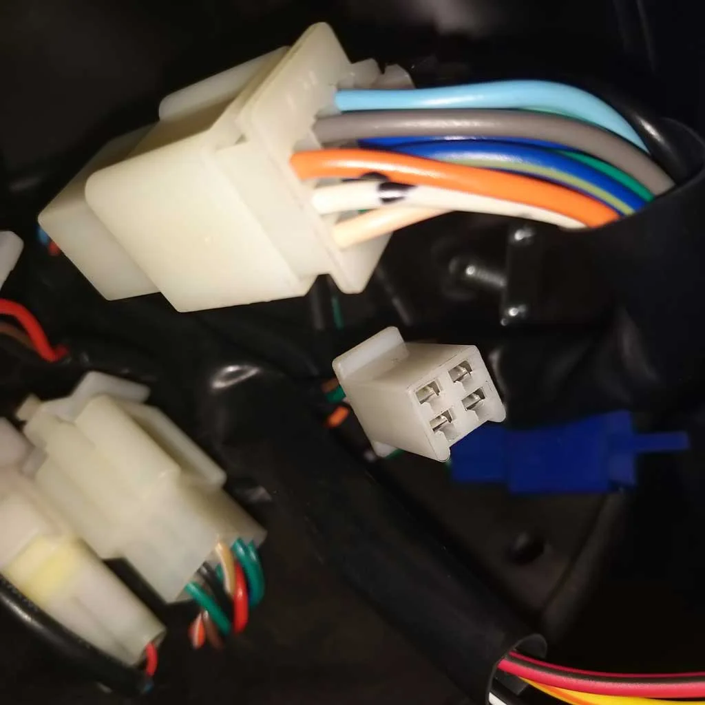
This first run uses the eBay switchgear and has the female socket at one end to connect to the chassis wiring, and a male socket to connect the bikes existing LH switchgear.
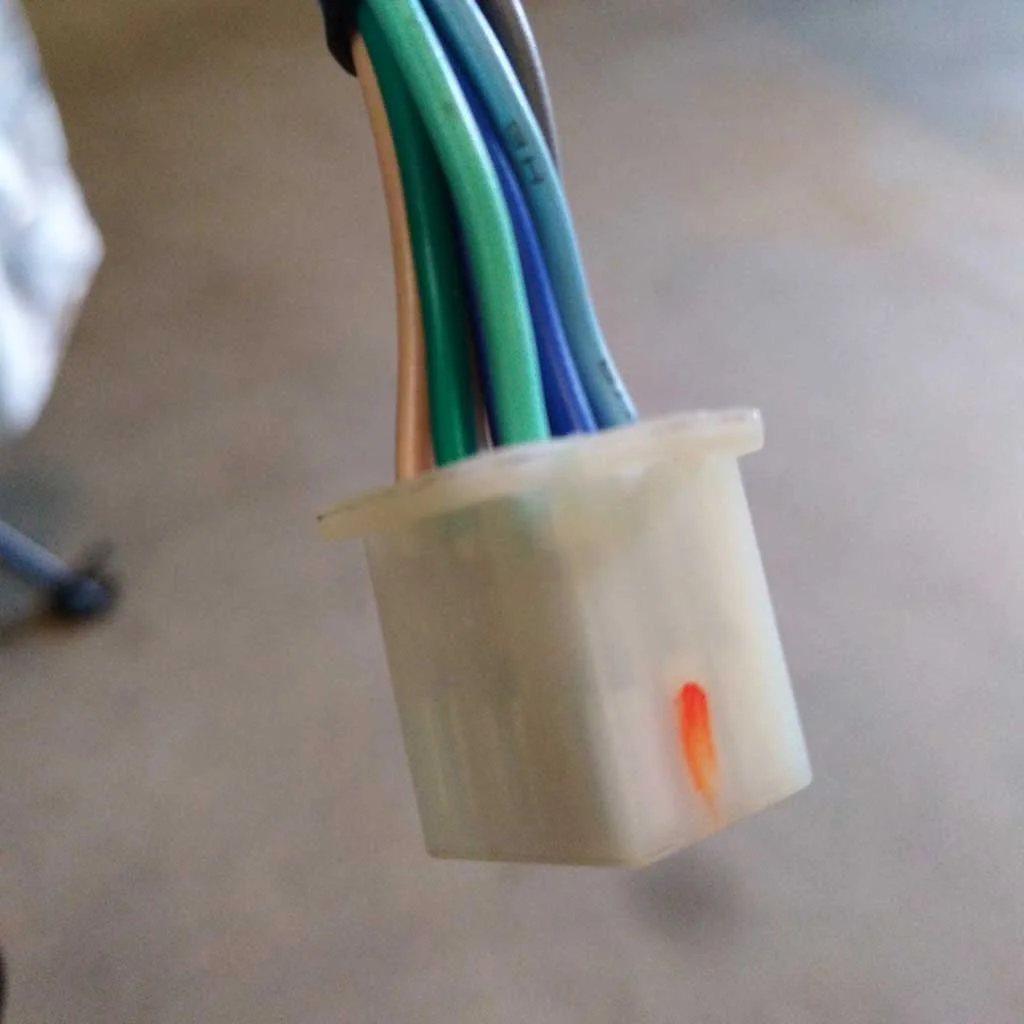
The eBay switchgear headlight switch is now the RH/LH turn signals - this switch originally had a brown wire which wasn’t needed and was discarded.
Of the original socket pins, on the bike, the clutch switch power and pass switch are reused - no pass/clutch on the eBay switchgear. The bikes original clutch switch is retained and activated by the combined clutch cables. I can live without the pass switch.
Images below show how soldering, and crimping terminals, works when you only have one arm.

Magnets are an arm amputees best friend.

Crimp tool is fixed in the vice and my short arm does the crimping while my fat fingers try to keep the wires and crimp together.

Finished arrangement, with test loom connected to the socket for the existing LH switchgear.

Tested - works! In a perfect world it’ll work when connected to the bike.
Pillion foot peg brackets = crash bars?
If you take a look at the Gran Milano you will notice the exhausts hang out there. So much so I’m pretty sure they’re going to get bent if I drop the bike.
There are no b=crash bars out there for this bike (yet) but in the box of goodies that came the bike were the pillion foot peg brackets. I wouldn’t use these “as is” fas protection for the exhaust, I’d want to do something nice that bolted up to the bike in their place.
To do this I started with a 3D scan of the part and modeled the part in its existing form. From here I’ll kick around a few ideas and let the budget decide which direction I go in. Watch this space.


Wiring in new controls - checking factory wiring
In preparation for the new controls I needed to confirm the bikes wiring matched that shown in the manual.
I did have to order another set of the switches that mount to the clutch lever perch, so that puts this stage of the project back a couple of weeks. This switch block I’m waiting on will be used for the starter button and kill switch.


CNC Arm Parts - DJ Design & Engineering
A few progress photos of the arm components being manufactured by Dan at DJ Design & Engineering. These look fantastic, and a big shout out to Dan for dialing in my tolerances and for the milling these out so quick.
Once complete these parts will be sent off to DNA Anodising - should look even better.


Controls, do we have a winner?
I think I have it now, and of course it was a $37 eBay part.
What I’m aiming for with the RH switchgear set is minimal width and the most amount of controls. Looks took a back seat on this one. I just needed to bring the clutch lever over as close to the handgrip as practical, and at the same time have the controls in easily operated positions.
The plan had been to use a separate throttle assembly and some LH side switchgear. With the throttle assembly width at 24mm it didn’t leave a lot of room before the clutch lever, and ultimately brake lever, were moved too far away. And this is why I was shelling out for compact switchgear like the K&S gear.
I took a gamble on this set from eBay as it included a throttle tube housing - with the right attachment point for the SWM throttle cable. Quality overall isn’t too shabby; aluminium housing, switches seem fine even if their fit in the housing isn’t perfect. There is a small locating pin on the rear shell of the housing which will have to, if it doesn’t align with what is on the handlebar now. The current labelling will have to go, and hopefully replaced.
Overall width is 48mm, or 44mm if I trim down a small lip to the left hand side of the housing. Assuming I take out the lip this assembly brings my clutch and brake levers 11mm toward the throttle grip. Real Estate on the handlebar is hard to come by with all of the controls in one place, so 11mm is a significant win.
Wiring this up will mean repurposing the 3 position headlight switch as my turn signals. Fortunately, the switch has the right contacts and wiring and should work. The starter button will become the horn switch, and the kill switch will become the hi/lo switch for the headlight. The plan being to wire all of this in while retaining the bikes standard LH side switchgear. Start and kill switch are in a separate housing, bolted to the back of the clutch lever perch.


More Controls
I’ve abandoned the two functional clutch levers setup I was so keen on. Instead, I’m running a bit of a compromise; the original clutch lever and cable remain and can be easily changed over for a two-armed rider. I’ve added two cable clamps; one to keep the second clutch cable up and out of the way (more presentable) and a small clamp to tie the two clutch cable inners together. The two cable inners operate together to activate the clutch switch.
The original front brake lever is replaced by a short brake lever to improve my emergency stops; index and middle finger operate the brake while ring and little finger operate the clutch lever. Seems to work so far.
360 degree video of the clutch being punished.

Two clutch cables and clamps.

Clutch and brake lever set up.
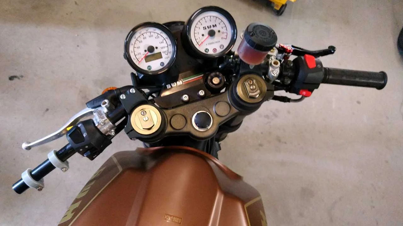
Current state of the handlebars and controls.
Shock Absorber
I had this Float X2 tuned by the guys at The Mountain Bike Suspension Center - these guys were great, fast professional and the results are perfect.
The Float X2 was the shock I designed the arm around originally, but found the DnM and thought I’d be saving money.
This replaces the DnM shock that was over-sprung - the DnM cannot be revalved. Fortunately, the DnM isn’t an expensive shock absorber, and I have a use for one I have. With some additional plates I can reconfigure the motorbike arm to provide assistance in completing a chin-up; adjusting the shock as my strength improves.
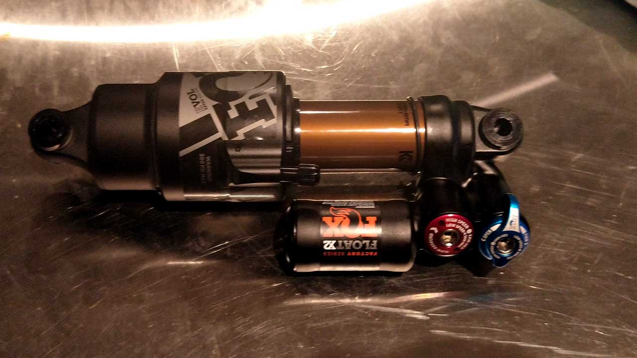
Fox Float X2

More switchgear
The latest two switchgear options.
First one is a full set of K &S Technologies switchtgear. Part numbers 12-0055 and 12-0055CN. Check them out HERE . I bought these through eBay from Alchemy Parts in the UK. These were not cheap, but the quality is worth it. Total cost $145 AUD.
The second contender appears to be a cheap knock off of the K&S Tech part. This set isnt terrible though. the housing is cast aluminium, the wiring isn’t too bad and the switches (though cheesy looking) appear quite robust. The indicator switch on this set feels more positive and natural compared to the K&S set. Total cost $16 AUD.
These two fill the gap between being compact and appearing intuitive. Both house only three of the six switches required and will leave me to fill out the starter button and kills switch using the 2 x switch housing from eBay. This thing isnt too bad either, bulky and weird looking but well made. I’ve switched out one of the red latching switches for a green momentary switch (starter) leaving the remaining red latching switch as my Kill switch.
The Pass switch is the only switch I have left to sort out, and to be honest I’m going to try wing it without ia Pass switch.
I have three other options on their way before I make a decision on which way I’m going with this.

K&S Technologies switchgear.

Inside look at the K&S Technologies switchgear.

Cheap eBay switchgear

Inside look at the eBay switchgear.